Pre-Silicon Test Pattern Validation, Debug, and Re-target Solution


Scan and functional patterns (ATPG, BIST, STIL, WGL, various ATE formats), including those from IP-core vendors, can be validated with the designer's DUT model for advanced preparation of test patterns, and more importantly, to perform early detection of problems that would cost millions of dollars if they slipped through tape-out into mask and silicon manufacturing processes.
Solstice-PV changes the way design and test interact.
Design verification engineers can generate and validate their own test patterns or re-use a golden simulation flow in Solstice-PV's self-documented, executable flow-diagram to validate the converted patterns or ATE-specific patterns in the design simulation environment.
Test engineers can now get a head start in validating test pattern's functionality without the physical device. Instead of sending a problem report or screenshot of the waveform, test teams can communicate with the design team the precise failing location, the nature of the failure, and how the design team can reproduce the problem in the same simulation environment.
Using Solstice-PV is as easy as point-and-click. For example, to validate a STIL pattern from ATPG, there are 3 simple steps:
Viewing design and test data in one environment optimizes team communication and reveals the exact correlation of, for instance, a transition of an ATE pin in a tester cycle with a scan cell name, scan cycle and simulation timestamp. ATE time-set name can be mapped with an event sequence coded in a design testbench.
Solstice-PV's seamless integration with leading logic simulators enables immediate viewing of discrepancies between the expected state in the ATE patterns with that of the DUT. Solstice-PV's robust graphical user interface (GUI) shows strobe placement and type (edge or window), the nature of failure, and the correlation of the design timestamp vs tester cycle.
Textual logs of failure information are also available for post-processing purposes in any of the custom simulation environment.
Drag and drop an error log file into Solstice-PV's waveform editor to get a visual of the failures. Both EDA's error format (from simulators or ATPG tools) and STDF (ATE standard data failure format) are supported.
Simulation can be suspended with a mouse click in the Solstice-PV environment. The Edit-in-Place feature enables timing and pattern to be adjusted and then resume the simulation without Verilog re-compilation. This enables rapid troubleshooting by either the test or design verification team.
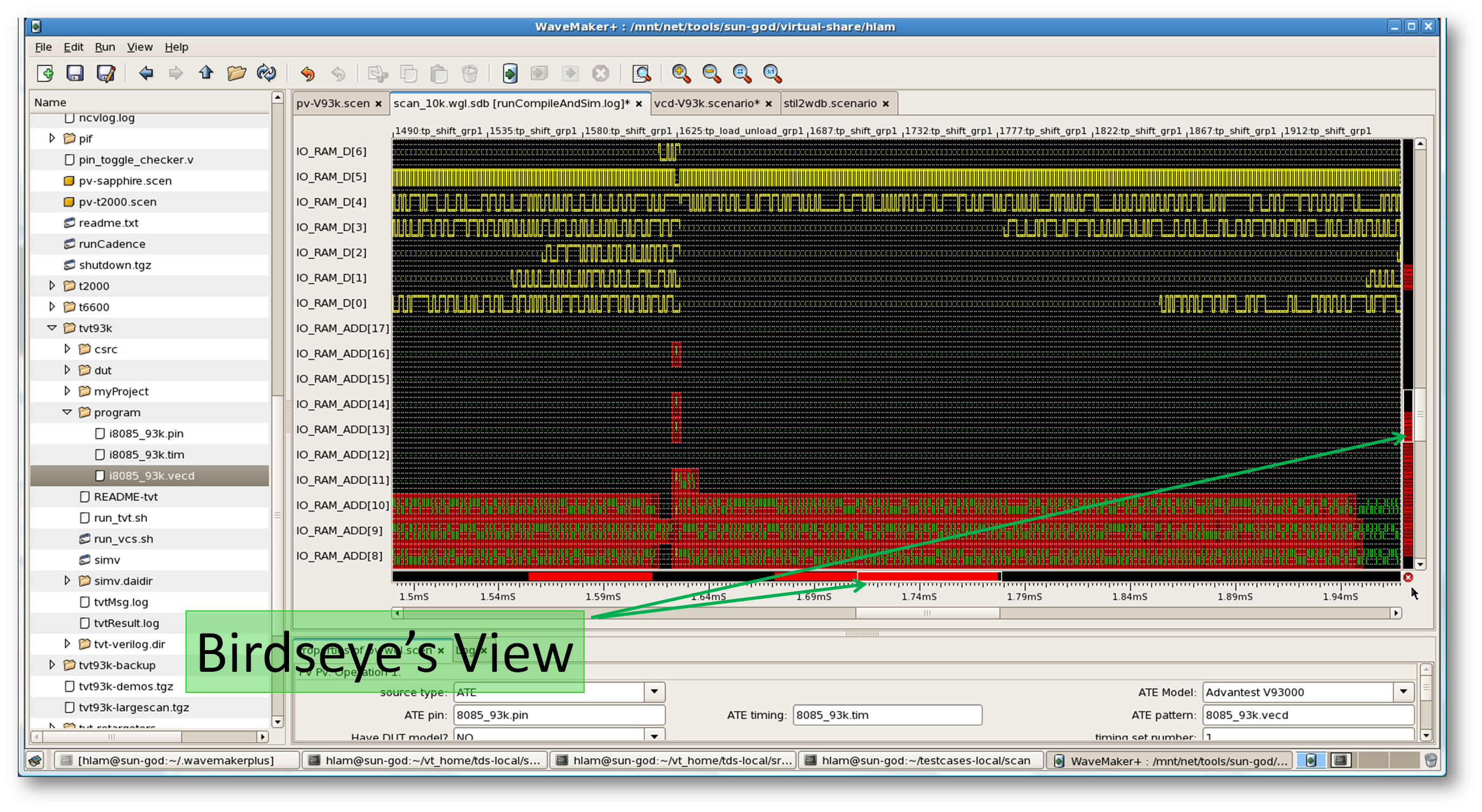
There are times when experience reins supreme. Your prototype part failed in billions of cycles among thousands of pins and many are embedded in scan chains. Viewing a certain signature of failures could be just the hint you needed to hone in to a particular area of the design or a region of test patterns. Whether you're in design or test, Solstice-PV's snappy waveform zooming capability (enabled by the latest database random access techniques) gives you an overview of whether the failure is in a checker pattern, corners, symmetrical, or otherwise.
The "birdseye" view also displays any concentrations of failing regions.
Similar to validating STIL files, ATE-specific patterns are set up and processed the same way. In the screen shot below, a set of Advantest V93000 files are being validated. It's a set of pin, timing, and binary pattern files. Timing set number, equation set number, and spec set number are three additional parameters required by the V93000 file. These can be entered in Solstice-PV's PropertySheet, and the rest is the same as the STIL example above.
